An overview of ultraviolet-induced degradation in silicon photovoltaic modules — mechanisms, affected technologies, testing standards, and mitigation strategies.
1. Definition and background
UV-induced degradation (UVID) refers to the loss of performance in photovoltaic (PV) modules caused by prolonged exposure to ultraviolet radiation, typically in the 280–400 nm wavelength range. It manifests as a reduction in open-circuit voltage, short-circuit current, and fill factor, ultimately lowering module power output. UVID can act at the encapsulant level (yellowing, embrittlement) or at the solar cell level (degraded surface passivation), and in modern high-efficiency modules, both mechanisms are frequently observed together.
UVID has become an increasingly prominent reliability concern over the past decade. Independent module reliability testing found that around 40% of commercial TOPCon (tunnel oxide passivated contact) modules tested in 2024 lost more than 5% of their rated power after a UV dose of just 60 kWh/m² — a dose reached in roughly one year under moderate irradiance, and considerably faster in high-UV regions such as Australia, the Middle East, or the Atacama Desert [1][2]. This has coincided with the PV industry’s move toward UV-transparent encapsulants, which improve module power by letting more of the incident spectrum reach the cell, at the cost of exposing cell surfaces to a much higher UV dose than older, UV-blocking formulations allowed [3].
2. Physical mechanism
At the cell level, UVID is driven by the interaction of high-energy UV photons with hydrogen-rich dielectric passivation films — principally silicon nitride (SiNx:H) and aluminium oxide (AlOx) layers used to passivate the silicon surface. Photons with energy above roughly 3.4 eV (wavelengths shorter than about 365–370 nm) carry enough energy to break silicon–hydrogen (Si–H) bonds, which have a bond energy of around 3 eV [4][1].
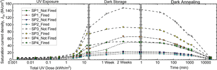
Breaking these bonds has two immediate consequences. First, it creates silicon dangling bonds at the passivation interface, which act as recombination-active defect states, quantified as an increase in interface defect density (Dit). This degrades chemical passivation and increases surface recombination. Second, it releases mobile atomic hydrogen, which can diffuse through the dielectric stack and re-accumulate at buried interfaces (for example, the AlOx/silicon interface beneath a SiNx capping layer), where it can form new defect complexes rather than being lost from the system [1].
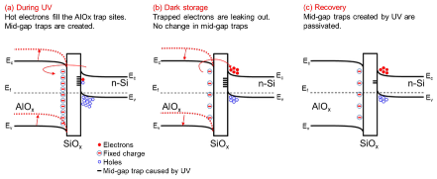
In parallel, UV exposure can generate energetic (“hot”) electrons that become trapped within the AlOx layer, increasing its negative fixed charge (Qf). Because negative fixed charge repels minority carriers (electrons) from a p-type surface, this initially improves field-effect passivation. The net effect of UVID on a given cell is therefore a competition between worsening chemical passivation (via Dit) and (temporarily) improving field-effect passivation (via Qf) — in practice, the chemical damage dominates and cells still show a net loss in carrier lifetime and efficiency [5][6].
A further complication is that degradation does not necessarily stop once the UV source is removed. Some AlOx-passivated structures exhibit “dark storage degradation,” in which performance continues to decline for days to weeks after UV exposure ends, a phenomenon attributed to the slow de-trapping of charges responsible for the temporary field-effect boost, as shown in Figure 1. Subsequent thermal annealing (of the kind that occurs during cell firing or dedicated recovery bakes) can drive the accumulated hydrogen back into the silicon bulk, largely restoring chemical passivation, though infrared spectroscopy shows this leaves a permanent structural rearrangement of the dielectric stack behind, even after electrical performance recovers [6].
3. Role of encapsulants and module design
UVID is not confined to the silicon cell itself. The polymer encapsulant — historically ethylene-vinyl acetate (EVA) — is also susceptible to UV-driven photothermal degradation. Prolonged UV exposure combined with heat and moisture breaks down the EVA polymer, generating polyconjugated chromophore species that cause the encapsulant to yellow or brown, and releasing acetic acid as a by-product [7]. Discoloured encapsulant absorbs more blue and violet light, reducing light transmission to the cell and cutting short-circuit current, while the acetic acid produced can corrode cell metallisation, solder joints, and interconnect ribbons, and accelerates further encapsulant yellowing autocatalytically [7][8]. In older glass–backsheet module designs, acetic acid can diffuse out through the backsheet; in glass–glass modules this escape path is largely blocked, which can trap corrosive by-products against the cell [2].
To improve module efficiency, manufacturers have increasingly adopted encapsulants with higher UV transparency (including polyolefin-based materials) in place of traditional UV-cutting EVA formulations. This raises energy yield but simultaneously increases the UV dose reaching the cell surface, directly increasing exposure to cell-level UVID [3].
4. Affected cell technologies
UVID is more pronounced in modern high-efficiency cell architectures than in older designs such as aluminium back surface field (Al-BSF) cells. TOPCon, PERC, and heterojunction (HJT) cells all rely on thin dielectric passivation stacks with a high hydrogen content and design choices (higher emitter sheet resistance, thinner anti-reflection coatings, more UV-transparent films) that were optimised for efficiency rather than UV hardness, and this has made them measurably more sensitive to UV exposure [3][9].
TOPCon cells, which have overtaken PERC as the dominant industrial cell architecture, are a particular focus of current research. Their front-side AlOx/SiNx passivation stack degrades under UV exposure in the manner described above, while the rear side — protected by a doped polysilicon layer roughly 100–150 nm thick — is comparatively UV-resistant. Optical simulations show that this polysilicon layer strongly absorbs incident UV radiation below about 370 nm, shielding the underlying ultra-thin tunnel oxide from UV damage. This makes the rear side of standard-thickness TOPCon cells well suited to bifacial applications, although thinning the polysilicon layer (a common strategy to reduce parasitic light absorption) reduces this natural UV shielding and would be expected to increase rear-side UVID susceptibility [1].
Wavelength matters as much as total dose: UV-B radiation (280–315 nm), though it makes up only around 1.5% of the UV present in the standard terrestrial solar spectrum, carries higher photon energy than UV-A (315–400 nm) and breaks proportionally more Si–H bonds. Experiments comparing equivalent doses show UV-A and UV-B ultimately drive the same type and extent of degradation in TOPCon cells, but UV-B does so far faster — a property that can be exploited to accelerate laboratory UVID testing, since most qualification standards under-represent UV-B relative to natural sunlight [1].
HJT cells show a somewhat different profile: their degradation has also been linked to Si–H bond breaking and hydrogen loss from passivation layers, but several studies report that HJT UVID is comparatively more reversible with moderate heating, in contrast to the more persistent structural changes seen in TOPCon stacks [10].
5. Interaction with other degradation modes
UVID does not act in isolation. It has been shown to interact with, and in some cases suppress or accelerate, other known PV degradation mechanisms.
Light- and elevated-Temperature-Induced Degradation (LeTID), a hydrogen-related bulk defect that typically appears in fired cells held at moderately elevated temperature, is notably absent in cells that are exposed to UV radiation during the same thermal treatment, even though it appears clearly in dark-annealed controls held at an identical temperature without UV. This suggests UV exposure meaningfully redirects bulk hydrogen dynamics, likely by pulling hydrogen toward the surface rather than leaving it to form the bulk defects responsible for LeTID — though the precise interaction is still an active research question [1].
Damp heat degradation can be worsened by prior UV exposure: UV-damaged regions of a module have been shown to generate higher concentrations of acetic acid during subsequent damp-heat exposure, accelerating corrosion at the gridline/cell interface and producing greater series-resistance losses than damp heat alone [11].
6. Testing standards and their limitations
The principal qualification standard for crystalline silicon modules, IEC 61215-2 (test MQT10), specifies a UV preconditioning dose of only 15 kWh/m² in the 280–400 nm range at a module temperature of 60 ±5 °C — equivalent to only around 46 days of field exposure in a high-irradiance location such as Arizona [12][2]. IEC 61730 (safety qualification) requires a higher 60 kWh/m² dose, and the updated “Quality Plus” protocol recommends 225 kWh/m², but even this is only roughly equivalent to two years of field exposure in a strong UV climate — far short of a 25–30 year warranted module lifetime [13][2]. Recent independent studies have found that a UV stress of around 4.5× the current MQT10 dose (roughly 67.5 kWh/m²) was needed to reproduce the Voc, Isc, and external quantum efficiency losses seen in fielded modules, reinforcing that current standard testing likely under-detects long-term UVID risk [14].
This gap matters because standard tests were developed before UVID was recognised as a major failure mode for high-efficiency cells, and they do not account for how real UV dose varies by climate, tilt angle, or mounting configuration (see below). More rigorous protocols exist for material-level testing (e.g. IEC TS 62788-7-2, up to 100 kWh/m²) and accelerated aging procedures used by research institutions (60–80+ kWh/m², sometimes combined with damp heat), but none yet fully replicate multi-decade field exposure, and there is growing consensus in the literature that region-specific, dose-realistic testing thresholds are needed [2][15].
7. Climate and system design dependence
The UV dose a module actually receives in the field depends strongly on geography and how the module is mounted. Global UV irradiance varies from under 30 W/m² in high-latitude regions to over 80 W/m² in arid zones, driven by differences in solar elevation, atmospheric ozone, cloud cover, and aerosols [2]. Modules in the Atacama Desert, the Sahara, the Middle East, and northern Australia experience among the highest annual UV doses in the world, with high-precision modelling showing fixed-tilt systems in these regions can accumulate over 100 kWh/m² of UV per year — several times the IEC 61215 qualification dose — well within a single year of operation [2].
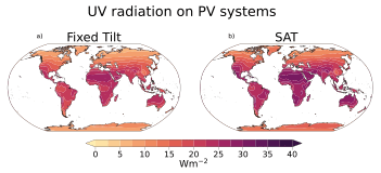
Mounting configuration adds a further factor. Single-axis tracking (SAT) systems, which continuously reorient modules to follow the sun, can receive up to around 20% more annual UV irradiance than fixed-tilt systems in the same location, because they maintain a more perpendicular angle of incidence to the sun through the day. Modelling of UV photodegradation rates combining UV dose, module temperature, and humidity shows this translates into substantially higher predicted degradation for tracked systems — up to roughly twice the degradation rate of fixed-tilt systems in arid and semi-arid climates, where UV exposure is already most intense [2]. This means two otherwise identical modules can experience meaningfully different UVID-driven lifetimes purely as a result of where, and how, they are installed.
8. Mitigation strategies
Several strategies have been proposed or demonstrated to reduce UVID risk, at both the material and system level.
Thicker AlOx passivation layers act as a more effective barrier to hydrogen transport, reducing the amount of mobile hydrogen able to reach and damage the critical passivation interface, and have been shown experimentally to improve UVID resilience compared with thinner films [6].
Preserving or engineering a UV-absorbing rear layer (such as an adequately thick doped polysilicon layer in TOPCon cells) can passively shield sensitive interfaces from UV photons, at some trade-off with optical parasitic absorption [1].
UV-resistant or UV-cut encapsulants reduce the UV dose reaching the cell, at the cost of some energy yield; balancing UV transparency against long-term reliability is an active area of encapsulant formulation research [3][16].
Thermal annealing / recovery bakes can redistribute accumulated interfacial hydrogen back into the silicon bulk, restoring much of the lost chemical passivation, though some structural change to the dielectric stack appears to be permanent [6].
Climate- and mounting-aware qualification testing — setting UV test doses and pass/fail thresholds based on a module’s intended installation climate and mounting configuration (fixed tilt vs. tracking) — has been proposed as a way to close the gap between standard qualification testing and real-world degradation risk [2].
References
- Khan, M.U., Sen, C., Pollard, M., Huang, T., Gao, M., Lv, R., Yu, Y., Wu, X., Wang, H., Wang, X., & Hoex, B. (2026). UV-induced degradation in TOPCon solar cells: Hydrogen dynamics and impact of UV wavelength. Solar Energy Materials and Solar Cells, 294, 113895. https://doi.org/10.1016/j.solmat.2025.113895
- Poddar, S., Liu, S., Hamer, P., Kay, M., & Hoex, B. (2026). Closing the UV-Induced Photodegradation Gap Through Global Scale Modeling of Fixed Tilt and Tracking Photovoltaic Systems. IEEE Journal of Photovoltaics. https://doi.org/10.1109/JPHOTOV.2026.3668778
- Thome, F.T., Meßmer, P., Mack, S., Schnabel, E., Schindler, F., Kwapil, W., & Schubert, M.C. (2024). UV-induced degradation of industrial PERC, TOPCon, and HJT solar cells: the next big reliability challenge? Solar RRL. https://doi.org/10.1002/solr.202400628
- Kamioka, T., Takai, D., Tachibana, T., Kojima, T., & Ohshita, Y. (2015). Plasma damage effect on ultraviolet-induced degradation of PECVD SiNx:H passivation. In 2015 IEEE 42nd Photovoltaic Specialist Conference (PVSC). https://doi.org/10.1109/PVSC.2015.7356326
- Gielis, J.J.H., Hoex, B., van de Sanden, M.C.M., & Kessels, W.M.M. (2008). Negative charge and charging dynamics in Al2O3 films on Si characterized by second-harmonic generation. Journal of Applied Physics, 104. https://doi.org/10.1063/1.2985906
- Khan, M.U., Ciesla, A., Johns, A., Sen, C., Huang, T., Song, H., Gao, M., Lv, R., Yu, Y., Wu, X., Wang, H., Wang, X., & Hoex, B. Charge Trapping, Hydrogen Accumulation, and Structural Rearrangement: A Complete Model for Ultraviolet-Induced Degradation in TOPCon Devices. Manuscript in preparation, UNSW Sydney.
- Peike, C., Hoffmann, S., Hulsmann, P., Thaidigsmann, B., Weiss, K.-A., Koehl, M., & Bentz, P. (2018). The causes and effects of degradation of encapsulant ethylene vinyl acetate copolymer (EVA) in crystalline silicon photovoltaic modules: A review. Renewable and Sustainable Energy Reviews, 81(2), 2299–2317. https://doi.org/10.1016/j.rser.2017.06.028
- Uličná, S. et al. (2023). PV encapsulant formulations and stress test conditions influence dominant degradation mechanisms. Solar Energy Materials and Solar Cells, 255, 112319. https://doi.org/10.1016/j.solmat.2023.112319
- Ye, H., Huang, S., Qian, C., Sun, Z., Chen, Y., Song, X., Zhang, Y., Wang, N., Hu, Y., Yang, Y., Li, L., Ma, Z., Chen, T., Liu, W., & Yu, J. (2023). Short wavelength photons destroying Si–H bonds and its influence on high-efficiency silicon solar cells and modules. Solar RRL, 7. https://doi.org/10.1002/solr.202300334
- Razzaq, S. et al. (2025). Enhancing UV light stability in commercial silicon HJT solar cells and modules. Solar Energy, 298, 113735. https://doi.org/10.1016/j.solener.2025.113735
- Gaulding, E.A. et al. (2025). UV + Damp Heat Induced Power Losses in Fielded Utility N-Type Si PV Modules. Progress in Photovoltaics: Research and Applications. https://doi.org/10.1002/pip.70017
- IEC 61215-1:2021. Terrestrial photovoltaic (PV) modules – Design qualification and type approval – Part 1: Test requirements. International Electrotechnical Commission. https://webstore.iec.ch/publication/61345
- Wohlgemuth, J., & Kurtz, S. (2014). Photovoltaic module qualification plus testing. In Proc. IEEE 40th Photovoltaic Specialist Conference (PVSC), 3589–3594. https://doi.org/10.1109/PVSC.2014.6924883
- Gebhardt, P., Rivera, M., Fokuhl, E., Reise, C., Schnabel, E., Pander, M., & Hädrich, I. (2026). UV-induced degradation: comparative analysis of PV module testing and stabilization procedures against outdoor behavior. EPJ Photovoltaics, 17, 15. https://doi.org/10.1051/epjpv/2026007
- Kiwa PVEL. (2024). PV Module Reliability Scorecard. https://scorecard.pvel.com/uvid/
- Bonilla, R.S., Hoex, B., Hamer, P., & Wilshaw, P.R. (2017). Dielectric surface passivation for silicon solar cells: a review. Physica Status Solidi (A), 214. https://doi.org/10.1002/pssa.201700293
UV-Induced Degradation (UVID) | Hoex Group, UNSW
–navy: #0b2545;
–blue: #13315c;
–accent: #ffb703;
–text: #232323;
–muted: #5a5a5a;
–bg: #ffffff;
–panel: #f5f7fa;
–border: #e1e5ea;
}
* { box-sizing: border-box; }
body {
margin: 0;
font-family: “Segoe UI”, Helvetica, Arial, sans-serif;
color: var(–text);
background: var(–bg);
line-height: 1.7;
}
header {
background: linear-gradient(120deg, var(–navy), var(–blue));
color: #fff;
padding: 60px 24px 48px;
text-align: center;
}
header h1 { margin: 0 0 10px; font-size: 2rem; font-weight: 700; }
header p { max-width: 760px; margin: 0 auto; color: #dbe6f5; font-size: 1.02rem; }
.container { max-width: 860px; margin: 0 auto; padding: 44px 24px; }
nav.toc {
background: var(–panel);
border: 1px solid var(–border);
border-radius: 10px;
padding: 18px 24px;
margin-bottom: 40px;
}
nav.toc h2 { margin-top: 0; font-size: 1rem; text-transform: uppercase; letter-spacing: 0.5px; color: var(–navy); border: none; padding: 0; }
nav.toc ol { margin: 0; padding-left: 20px; }
nav.toc a { color: var(–blue); text-decoration: none; }
nav.toc a:hover { text-decoration: underline; }
section { margin-bottom: 46px; }
h2 {
color: var(–navy);
font-size: 1.4rem;
border-bottom: 3px solid var(–accent);
display: inline-block;
padding-bottom: 6px;
margin-bottom: 18px;
}
h3 { color: var(–blue); font-size: 1.1rem; margin: 22px 0 8px; }
p { margin: 0 0 14px; }
a { color: var(–blue); }
.infobox {
float: right;
width: 260px;
background: var(–panel);
border: 1px solid var(–border);
border-radius: 10px;
padding: 16px 18px;
margin: 0 0 20px 24px;
font-size: 0.9rem;
}
.infobox h3 { margin-top: 0; font-size: 0.95rem; }
.infobox dl { margin: 0; }
.infobox dt { font-weight: 600; color: var(–navy); margin-top: 10px; }
.infobox dd { margin: 2px 0 0; color: var(–muted); }
@media (max-width: 700px) {
.infobox { float: none; width: auto; margin: 0 0 24px; }
}
.fig-card {
background: var(–panel);
border: 1px solid var(–border);
border-left: 4px solid var(–accent);
border-radius: 8px;
padding: 16px 20px;
margin-bottom: 14px;
}
.fig-card strong { color: var(–navy); }
.fig-source { font-size: 0.85rem; color: var(–muted); }
ol.references { padding-left: 24px; }
ol.references li { margin-bottom: 12px; }
footer { text-align: center; padding: 30px 24px; color: var(–muted); font-size: 0.9rem; border-top: 1px solid var(–border); }
.clearfix::after { content: “”; display: table; clear: both; }


